
Monday, November 1, 2021
Friday, October 29, 2021
SolidCore CoreXY Updates
SolidCore CoreXY Updates
https://t.co/BaBMARnzel pic.twitter.com/B3Bq7slGuz
— 3D Distributed #MRRF2020 (@3ddistributed) October 29, 2021
Triple Z-Axis Motion & 3-Point Bed Leveling
Thursday, October 7, 2021
Duet 3 Wiring Guide
Duet 3 Wiring Guide

Duet Wiring Instructions
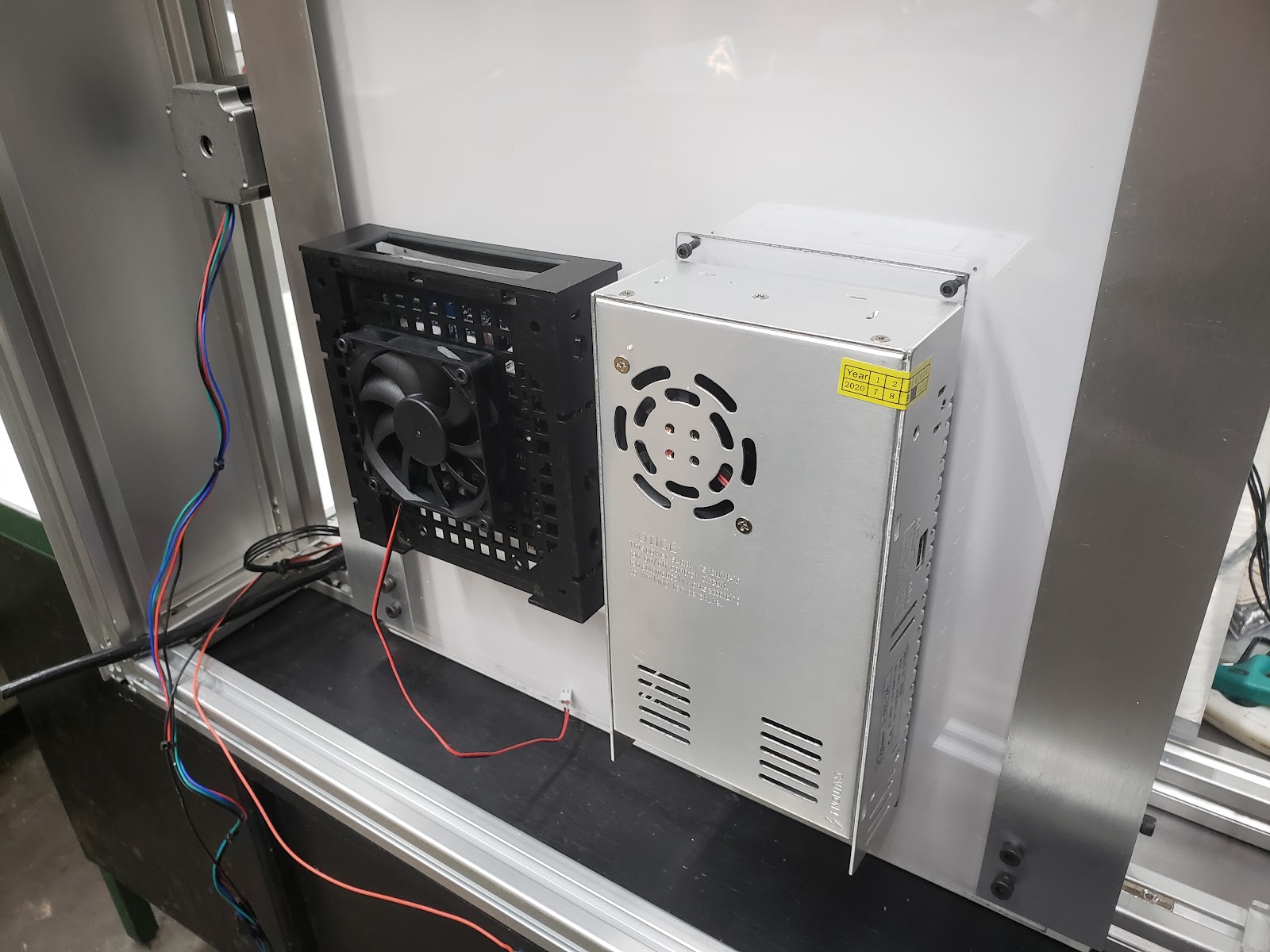
This is a guide on how to wire the Duet board for your printer. Once you have mounted the Duet 3 and 24v power supply to your 3d printer you can began to wire the Duet 3 Mainboard. I’m using the Duet 3 in standalone mode so I won’t be covering the Raspberry Pi.
Power Supply

Connect the Black wire into the “L” terminal Connect the White wire into the “N” terminal Connect the Green wire into the Ground terminal The wire colors meet US color standards for AC. Colors. The positive wire from the power supply goes to the terminal marked +. Do not solder the power supply wires because the heat generated from the current can melt the solder causing the connection to become loose. Duet3d recommends to use bootlace ferrules on the end of the wires and to re-tighten the terminal block screws after doing the first few prints, because heat generated by the high can cause them to creep and become loose.
Connect the terminal block labelled POWER IN to your power supply Make sure to get the polarity right and the wires you use are of proper gauge size to carry the current to supply the bed heater and electronics.
Letters or numbers to designate coils.

The standard is A+,A-,B+,B- (or B-.B+,A-,A+) on the labelling of Duet3d boards.
Stepper Motor Wire Color And Coil Pairs
Stepper Motor Color Coding of Wires & Coil Pairs
For any stepper motor to be wired up properly, we’ll need to determine which wires are “pairs” or connected to the ends of each coil. These are usually referred to as coil “A” and coil “B”. The exact order of the pairs Black/Green or Green/Black of pins does not matter, but keeping the pairs together on the left, and red/blue with each other on the right is important.
To get the motor moving properly and in the right direction stepper motors must be wired up properly. It does matter which coil is which and what the polarity of the coils. While there is no universal standard for color code for stepper motors, many stepper motor manufactures keep their stepper wires in order with the motor coil pairs
Black/Green is a motor coil
Red/Blue is a motor coil
Although the wiring colors can not be trusted the order of wires is usually as follows:
Wiring Option 1
1A – green
1B – black
2A – blue
2B – red
Wiring Option 2
A + black
A – green
B + red
B – blue
Sometimes Option
A + black (red)
A – green (green)
B + red (yellow)
B – blue (blue)
Determine which wires are “pairs” or connected to the ends of each coil. The motor wire pairs are known as coil “A” and coil “B”. The exact order of the pairs does not matter. Only keeping the pairs together is important
On the left
red/blue with each other
on the right
black/green with each other
Identifying The Stepper Motor Phases – Coil Pairs
If the color code and motor wiring isn’t allowing motor movement, ignore the wire colors and look at the wire positions instead. Use a multimeter to test to see if continuity in the wiring of the stepper – both motors behaved the same in that there was zero resistance between blue and red , zero resistance green and black.
Here are two ways you can pair the stepper motor wires into phases:
Using a multimeter, check for resistance. There should be a few ohms resistance between two wires that belong to the same phase, and no continuity between wires that belong to different phases.
With the motor wires not connected to anything, spin the motor shaft. Short two of the wires together, then spin the shaft again. If it is much harder to spin than before, those two wires belong to the same phase. Otherwise, try again with a different pair of wires shorted together.
Use a multimeter to find the coils and wire appropriately. ohm test the stepper motors. A wire pair should have a slight resistance. If the resistance values are right. The XYZ motors are rated 4.2V 1.5A 2.8 Ohm +/-10%. The extruder motor is rated 2.6V 1A 2.6 Ohm +/-10%.
Check for resistance. There should be a few ohms resistance between two wires that belong to the same phase, and no continuity between wires that belong to different phases.
With the motor wires NOT connected, spin the motor shaft. Short two of the wires together, then spin the shaft again. If it is much harder to spin than before, those two wires belong to the same phase. Otherwise, try again with a different pair of wires shorted together.
Bipolar Motors
Bipolar motors have two separate coils:
Red/Green is one coil
Blue/Yellow is the other coil.
Use a multimeter to find the coils and wire appropriately. ohm test the stepper motors. A wire pair should have a slight resistance. If the resistance values are right. The XYZ motors are rated 4.2V 1.5A 2.8 Ohm +/-10%. The extruder motor is rated 2.6V 1A 2.6 Ohm +/-10%.
Also See
Wednesday, October 6, 2021
Best CoreXY 3D Printers 2021
Best CoreXY 3D Printers 2021

Choosing a corexy printer design can be a challenge with so many design options available. Every CoreXY design has different design goals for different needs as well as different compromises. Whether you’re building a new printer or just in need of a new 3d printer, there are many options to choose from with each of them having their own unique advantages and disadvantages.
Size vs Speed
Cost vs Accuracy
Size vs Volume
Depending on your application there are many options to choose from.
DIY 3D Printer Kits
Design and Build Plans
Plug and Play- Ready to Print
New Projects Soon To Be Released
All Metal Parts
WHAT IS THE BEST COREXY DESIGN?
COREXY DIY DESIGNS & KITS
- Jubilee
- SecKit
- Voron 3D Printer
- BLV MGN Cube
- Railcore
- HyperCube
- E3D ToolChanger
- VzBot
- CrazyCreatorCube
- HeVort DIY 3D Printer
- SolidCore CoreXY
HeVort DIY 3D Printer

The HeVort changes the way 3d printers level the bed. Although non-planar printing is not really widely implemented yet, we may see more non-planar printing in the future. This would allow you to print a part in vertical mode and add another component at an angle without need of support material or other mechanical aids.
HeVort Z-Axis Design

JUBILEE 3D PRINTER

Jubilee corexy is one of the most hackable 3d printers. If your looking for a highly customizable printer you’ll have to take a look at this. It’s a multi-tool motion platform that has made much progress in the last year. Out-of-the-box, Jubilee is configured for multimaterial 3D printing compatible with current E3D toolchanger parts. Jubilee is meant to be extended by the community through custom tools and applications.
- Modular Platform
- ToolChanger
- Customizable
- Awesome
The Jubilee toolchanging platform was quick to adopted as manufactures began to offer all-metal upgrades for the platform. Mandala Rose Works offers a range of lightweight machined parts. The Tool changer platform has a big community on Discord.
Rat-Rig V-Core 3

The Ratrig V-Core 3 is a premium DIY kit for your CoreXY needs. The “Configurable” kit is simple for beginners but built with advanced users in mind. The Rat Rig V-Core is quickly getting traction with a growing community that’s pushing the limits of corexy scalability as many are diving into 3d printer builds as big as 500mm x 500mm x 500mm.
CrazyCreatorCube

The CrazyCreatorCube is a new project that is the alpha state as it launches it’s new open source design. The tool-changing 3D printer can utilize up to four extruders at a time. The tool holder uses neodymium magnets to mount the tools into the tool stations with a mechanical, latching mechanism. The central fan unit and air duct is optimized air flow. The CrazyCreatorCube has a well designed carriage well suited for belt tensioning.
- Build volume: 350x330x400mm
- ToolChanger Mechanism: Magnetic
- Open-Source
- Electronics: Duet2 with Duex5 Expansion Board
Voron 2.4

- Build volume: Scalable
- Extruder: AfterBurner
- Enclosure: Open or Enclosed
- Moving Gantry
- Electronics: Duet3D / Klipper
Voron 2.4 Specs
Light-Weight Carriage DesignHigh speed prints with fewer defects
Better at printing tall thin things
Great community support on Reddit
Less moving mass of the extruder carriage
BlackBox Multitool 3D Printer

Blackbox Specs
- Build Volume: 300 mm x 300 mm x 275 mm
- Full enclosure
- Direct drive toolchanger
- Water-cooled toolheads
- Belted Z-axis
- Automated leveling and calibration
- Price: $2,900
RailCore II 3D Printer
RailCore II 300ZL
The original Railcore printer is no longer available due to the updated 300 ZL and ZLT version. But here’s the details:- Linear Rails XYZ Axis
- 300mm x 300mm x 330mm Build Area
- ZLT is 300m x 300mm x 600mm Build Area
- Auto Leveling
- Hotend: E3D V6 or Mosquito
- 0.9 Degree Steppers
SecKit 3D Printer

SolidCore CoreXY

Related Content

Tuesday, October 5, 2021
Stepper Motor Holding Torque
Stepper Motor Holding Torque
This is the maximum torque that the motor can provide with both windings energized at full current before it starts jumping steps. The holding torque with one winding energized at the rated current is about 1/sqrt(2) times that.
Torque
The torque is proportional to current (except at very low currents), so for example if you set the drivers to 85% of the motor rated current, then the maximum torque will be 85% * 0.707 = 60% of the specified holding torque.
Motor Windings
Torque is produced when the rotor angle is different from the ideal angle that corresponds to the current in its windings. When a stepper motor is accelerating, it has to produce torque to overcome its own rotor inertia and the mass of the load it is driving. In order to produce this torque, the rotor angle must lag the ideal angle. In turn, the load will lag the position commanded by the firmware.
Microstepping
Microstepping can reduce torque. What this really means is that when the lag angle is assumed to be equal to the angle corresponding to one microstep (because you want the position to be accurate to within one microstep), higher microstepping implies a smaller lag angle, hence lower torque. The torque per unit lag angle (which is what really matters) does not reduce with increased microstepping. To put it another way, sending the motor a single 1/16 microstep results in exactly the same phase currents (and therefore the same forces) as sending it two 1/32 microsteps, or four 1/64 microsteps, and so on.
Also See
Triple Z Setup
SolidCore CoreXY - Triple Z Setup

Bed Leveling
Bed leveling is necessary in order to print large objects. Mesh bed leveling creates a virtual grid of the print bed. As the layers are printed the motors will lower and raise the nozzle while printing to compensate for the uneven locations on the build plate. Auto Bed Leveling is a function of the Duet 2 board itself.
Firmware
- Specify at least 3 points using the G30 command and after.
- Last one you need to add the S Parameter. Then it will level automatically
- Heat up build plate
- Click the “Bed Leveling” button or macro on the Duet Interface.
SolidCore Triple z Mechanism
The advantage of triplez is the additional degree of freedom which allows radial movement and bed leveling. With small springs on corners and the bed fixtures of the bed. Due to thermal expansion the aluminum plate just loses the frame.
Triple Z bed leveling using the Kinematic coupling for bed leveling and mounting.
Wider belts are more rigid and reduce artifacts caused by the elasticity of the belt itself. The artifacts in prints look like the pitch of the belt itself. In addition, increasing the size of the pulleys will reduce ringing and artifacts.
Related Content
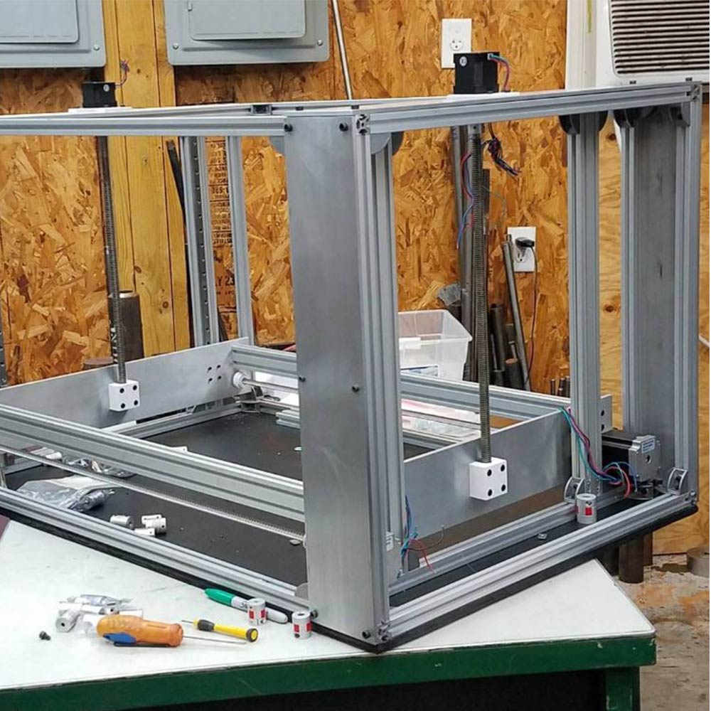
WorkHorse Printer-Z-Axis Design
WorkHorse Printer-Z-Axis Design

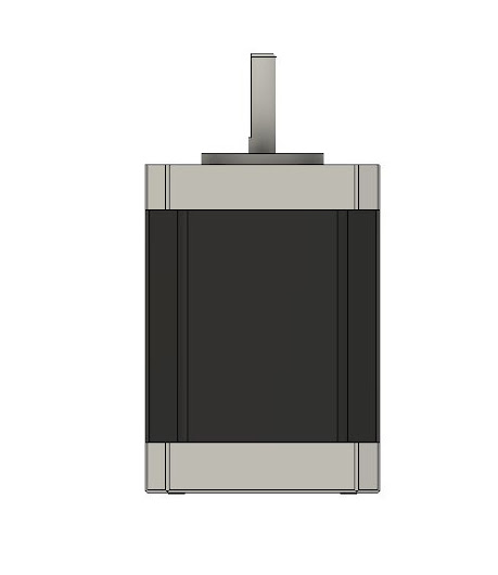
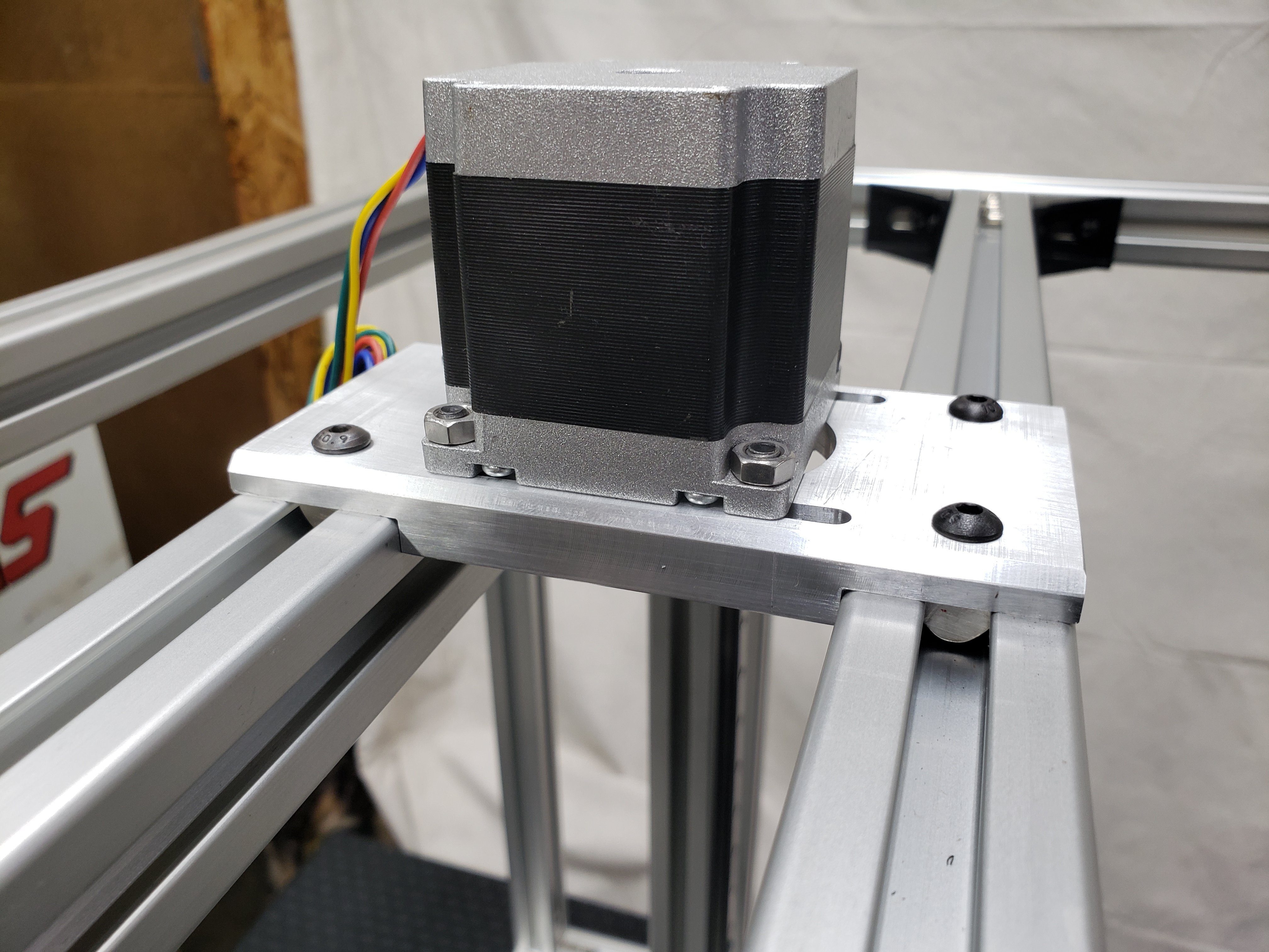
Z-Motor Mount Sizes
Nema 23 Mount
3030 Frame
2020 Frame
2040 Frame
Nema 17 Mount
2020 Frame
2040 Frame
Z-Axis Lead Screw To Gantry Plate Mount

Old Z-Axis Lead Screw To Gantry Mount
Related Content
Monday, October 4, 2021
WorkHorse Printer Y-Carriage Assembly
WorkHorse Printer Y-Carriage Assembly

The Y-axis carriage design for the WorkHorse 3D Printer has been updated. This carriage design will fit on the Workhorse V1 and V2 designs. The carriage mounts to MGN12h linear rails which have a 20mm x 20mm hole pattern.
- More M3 Taped Holes
- New Hotend and Extruder Mounting Locations
see Y-Carriage
WorkHorse V2


Duet 2 Wifi Setup
Duet 2 Wifi Setup
Use this for your Workhorse Printer Setup but with Duet 3 Setup
Connect the Duet to your PC with the USB cable provided. Do not connect other power supplies at this stage.
Windows users, download the USB drivers for Duet here and extract the files to a suitable location.
Install Drivers.
Download YAT Terminal Interface.
Setup YAT to use <LF> as the end of line character. Go to "Terminal" Menu -> "Settings" -> "Text Settings" -> "EOL sequence:" set to <LF>
Windows Users: Open YAT, and configure the correct COM port.

send command M115
The WiFi module has a blue LED on it, just next to the Micro SD card holder. This should flash once when power is connected to the board, but will only be lit permanently when connected to a WiFi network. Duets with an external antenna use a different WiFi module with no LED; if you have one of these, don't forget to plug in the external antenna!
Send M552 to check the status. It should say "WiFi module is disabled". Now put it into idle mode by sending command M552 S0. Send M552 again to check it's idle, then proceed to the next step.
Related Content
Workhorse Printer
Duet3D
Saturday, October 2, 2021
VzBot 3D Printer
VzBot 3D Printer

The VZbot is a very new corexy 3d printer project by Simon Vezina of Vez3D. The VzBot Printer is a high-speed 3d printer with a simple corexy design that uses less parts compared to core xy printers such as the Voron. The VzBot 3d printer is capable of 3d printing at high speeds. Fewer parts means less components can break and buying parts or troubleshooting is easier.
VzBot Build

VzBot Parts
The VzBot 3D Printer project caught my attention because the mechanical arrangement is similar to the SolidCore CoreXY 3D Printer.
Related Content
Friday, July 2, 2021
3D Printer Build - Calculating Wire Gauge
3D Printer Build - Calculating Wire Gauge
Most 3d printers use either 12V or 24V
Hotend 12V heater cartridge can draw up to 4A
A heated bed can draw nearly 12A.
Cheaper 26-gauge wire are rated at 2 amps
If your wire gauge is not large enough or longer than needed the resistance will be higher This means less watts going through the wire.
Copper wire size uses the American Wire Gauge (AWG). The lower the gauge number, the less resistance the wire has and therefore the higher current it can handle safely.
Stepper Motor Wiring
Rated Current is the maximum current that can pass through both windings at the same time. Set the motor current to no more than about 85% of the rated current. To get maximum torque out of your motors without overheating them, you should choose motors with a current rating no more than 25% higher than the recommended maximum stepper driver current.
Nema 17 Stepper Motors: 22 AWG wire with 4 conductors
NEMA 17 motor wires are 26 AWG
Most motor torque data assumed 24 Volts, at 1.1 amp to 1.5 amp. Roughly 26 to 36 Watts, but remember that's "chopped" or pulsed.
Wire size is based on power transmission requirements and length of wire.
10 gauge wire - 30 amps
12 gauge wire - 20 amps
14 gauge wire - 15 amps
16 gauge wire - 10 amps
18 gauge wire - 7 amps
20 gauge wire - 3 amps (or slightly more)
22 gauge wire - 2 amps
Stranded wire is best for lengthening motor wires, get 9 strands or more. Solder properly and heat shrink. 20 AWG or larger.
Use a shielded 4-core high current wire, so that the wiring creates much less capacitive and induced interference or a twisted pair of twisted pairs.
Each individual winding should have a twisted pair, and these two pairs should be twisted (in the opposite sense) together. Twisted pair will reduce induced interference to a minimum, and twist-on-twist is a very flexible way to combine 4 wires. Alas the construction will couple capacitively to nearby signal cables, so it pays to keep separate from them, or ensure all signal cables are shielded. (Signal cables are things like limit switch wiring, encoders, etc...).
Using a cordless drill and a bench vice, keep enough tension to prevent kinking, and reverse briefly to lose any torsion before releasing the wires.
Wire Connectors
The Molex 4 pin connector are rated at about 14 Amps (.093 inch / 2.36 mm diameter terminals.
Wire Gauge Chart
Motor Current
Maximum motor current 1.5A peak => Stepper motor rated current <= 1.9A
Maximum motor current 2.5A peak => Stepper motor rated current <= 3.0A
Maximum motor current 1.6A peak with good fan cooling => Stepper motor rated current <= 1.7A.
Use motors with lower rated current (e.g. 1.0 to 1.2A) and 24V power, then the drivers will run cooler.
Duet 3 Current
Duet 3 Mainboard 6HC and Expansion board 3HC has a recommended maximum motor current 6.3A peak/4.45A RMS) => Stepper motor rated current <= 6A
Duet 3 Toolboard has a recommended maximum motor current 1.4A peak) => Stepper motor rated current <= 1.75A
2B 2A 1A 1B
One solution is twisted pairs of wire to have one wire carrying the current while the other brings the current back.
Calculating the wire size
A higher voltage means a lower current for the same amount of power. This gives you the opportunity to use smaller wires for the same job. Voltage is proportional to the current. A higher voltage means a lower current. Wire size influences the amount of current that can pass through it.
A thicker wire will have less resistance per length
Less resistance means loss
The less loss means less temperature increase
In terms of wire size, 24V has an advantage over 12V, as the wires can be much smaller.
A power supply of 300 watts running at 12V or 24V, will use less wire.
Wire Sizing Chart and Formula
Calculate the Voltage Drop Index (VDI) using the following formula:
VDI = AMPS x FEET ÷ (% VOLT DROP x VOLTAGE)
Determine the appropriate wire size from the chart above.
To compensate for voltage-drop, heat and current changes it is recommended to use 6 gauge wire and 4 gauge for over 15 feet.
Subscribe to:
Posts (Atom)
-
SolidCore CoreXY - Triple Z Setup A perfectly levelled print surface becomes more challenging as the size of the build plate increases. Wit...
-
Duet 2 Wifi Setup Use this for your Workhorse Printer Setup but with Duet 3 Setup Connect the Duet to your PC with the USB cable provided....
-
Stepper Motor Color Coding of Wires & Coil Pairs For any stepper motor to be wired up properly, we’ll need to determine which wires are ...

