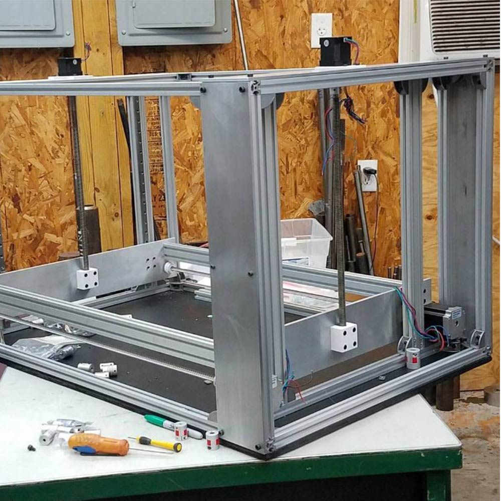
WorkHorse Printer-Z-Axis Design

Z-Motor Mount Sizes
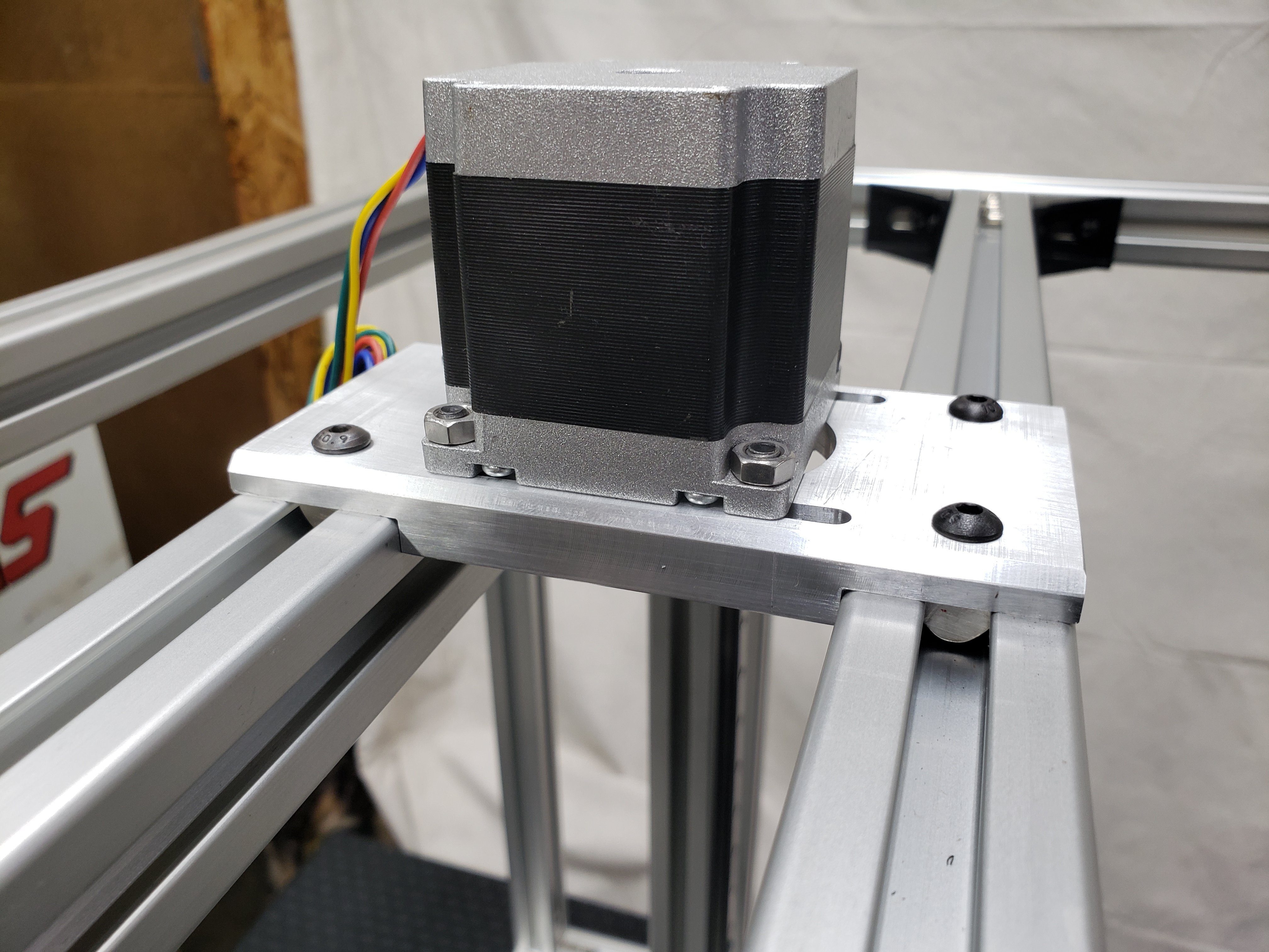
Nema 23 Mount
3030 Frame
2020 Frame
2040 Frame
Nema 17 Mount
2020 Frame
2040 Frame
Z-Axis Lead Screw To Gantry Plate Mount

Old Z-Axis Lead Screw To Gantry Mount

The Y-axis carriage design for the WorkHorse 3D Printer has been updated. This carriage design will fit on the Workhorse V1 and V2 designs. The carriage mounts to MGN12h linear rails which have a 20mm x 20mm hole pattern.


Use this for your Workhorse Printer Setup but with Duet 3 Setup

Connect the Duet to your PC with the USB cable provided. Do not connect other power supplies at this stage.
Windows users, download the USB drivers for Duet here and extract the files to a suitable location.
Install Drivers.
Download YAT Terminal Interface.
Setup YAT to use <LF> as the end of line character. Go to "Terminal" Menu -> "Settings" -> "Text Settings" -> "EOL sequence:" set to <LF>
Windows Users: Open YAT, and configure the correct COM port.
send command M115
The WiFi module has a blue LED on it, just next to the Micro SD card holder. This should flash once when power is connected to the board, but will only be lit permanently when connected to a WiFi network. Duets with an external antenna use a different WiFi module with no LED; if you have one of these, don't forget to plug in the external antenna!
Send M552 to check the status. It should say "WiFi module is disabled". Now put it into idle mode by sending command M552 S0. Send M552 again to check it's idle, then proceed to the next step.


Most 3d printers use either 12V or 24V
Hotend 12V heater cartridge can draw up to 4A
A heated bed can draw nearly 12A.
Cheaper 26-gauge wire are rated at 2 amps
If your wire gauge is not large enough or longer than needed the resistance will be higher This means less watts going through the wire.
Copper wire size uses the American Wire Gauge (AWG). The lower the gauge number, the less resistance the wire has and therefore the higher current it can handle safely.
Rated Current is the maximum current that can pass through both windings at the same time. Set the motor current to no more than about 85% of the rated current. To get maximum torque out of your motors without overheating them, you should choose motors with a current rating no more than 25% higher than the recommended maximum stepper driver current.
Nema 17 Stepper Motors: 22 AWG wire with 4 conductors
NEMA 17 motor wires are 26 AWG
Most motor torque data assumed 24 Volts, at 1.1 amp to 1.5 amp. Roughly 26 to 36 Watts, but remember that's "chopped" or pulsed.
Wire size is based on power transmission requirements and length of wire.
10 gauge wire - 30 amps
12 gauge wire - 20 amps
14 gauge wire - 15 amps
16 gauge wire - 10 amps
18 gauge wire - 7 amps
20 gauge wire - 3 amps (or slightly more)
22 gauge wire - 2 amps
Use a shielded 4-core high current wire, so that the wiring creates much less capacitive and induced interference or a twisted pair of twisted pairs.
Each individual winding should have a twisted pair, and these two pairs should be twisted (in the opposite sense) together. Twisted pair will reduce induced interference to a minimum, and twist-on-twist is a very flexible way to combine 4 wires. Alas the construction will couple capacitively to nearby signal cables, so it pays to keep separate from them, or ensure all signal cables are shielded. (Signal cables are things like limit switch wiring, encoders, etc...).
Using a cordless drill and a bench vice, keep enough tension to prevent kinking, and reverse briefly to lose any torsion before releasing the wires.
The Molex 4 pin connector are rated at about 14 Amps (.093 inch / 2.36 mm diameter terminals.
Maximum motor current 1.5A peak => Stepper motor rated current <= 1.9A
Maximum motor current 2.5A peak => Stepper motor rated current <= 3.0A
Maximum motor current 1.6A peak with good fan cooling => Stepper motor rated current <= 1.7A.
Use motors with lower rated current (e.g. 1.0 to 1.2A) and 24V power, then the drivers will run cooler.
Duet 3 Mainboard 6HC and Expansion board 3HC has a recommended maximum motor current 6.3A peak/4.45A RMS) => Stepper motor rated current <= 6A
Duet 3 Toolboard has a recommended maximum motor current 1.4A peak) => Stepper motor rated current <= 1.75A
2B 2A 1A 1B
One solution is twisted pairs of wire to have one wire carrying the current while the other brings the current back.
A higher voltage means a lower current for the same amount of power. This gives you the opportunity to use smaller wires for the same job. Voltage is proportional to the current. A higher voltage means a lower current. Wire size influences the amount of current that can pass through it.
A thicker wire will have less resistance per length
Less resistance means loss
The less loss means less temperature increase
In terms of wire size, 24V has an advantage over 12V, as the wires can be much smaller.
A power supply of 300 watts running at 12V or 24V, will use less wire.
Calculate the Voltage Drop Index (VDI) using the following formula:
VDI = AMPS x FEET ÷ (% VOLT DROP x VOLTAGE)
Determine the appropriate wire size from the chart above.
To compensate for voltage-drop, heat and current changes it is recommended to use 6 gauge wire and 4 gauge for over 15 feet.